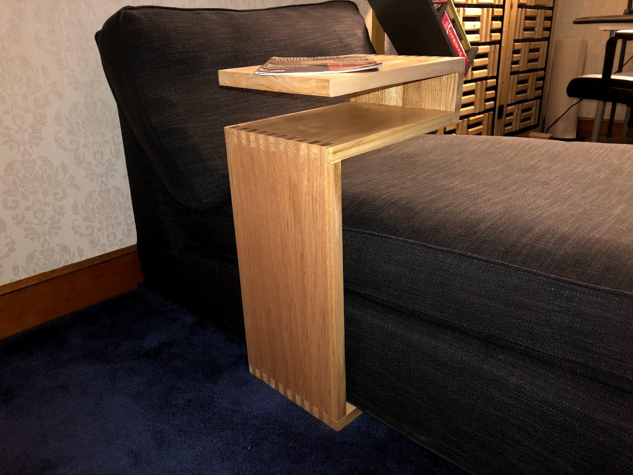


FINISHED C-TABLE


Last year my wife purchased a Chaise Lounge chair for her office and she asked me to make a table for it as she has been using it a lot more recently. So I did some research online and in keeping with the minimalist furniture design we have in the office I designed this style of table.
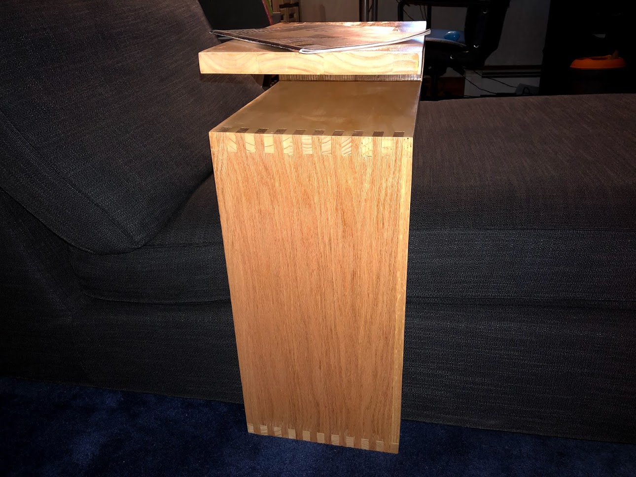
The table is shaped like the letter “C” so the base of the table can slide under the chair but still provide a table surface to put whatever you want on it, hence the name of the table. It only has 5 pieces to make it but the real challenge in making this table was the finger or box joint that is solely used in its construction.
Here is the steps of the project:
Design & Inspiration
Materials Needed
Wood Prep
Crosscutting the parts
The Box Joint Jig
Cutting the finger joints
Dry Assembly & Clamping Aids
Glue-Up
Sanding
Finished Table
DESIGN & INSPIRATION
Inspiration for this project came from Pinterest, there is an mage below of the idea. I still needed alter the measurements so it would suit my needs so I turned to my 3D modeling software called Sketchu and designed it it there.
The unit only has 5 parts to it and the overall size is 26” high x 15” wide x 9” deep, it has a shelf in it just below the tabletop surface and because there is o vertical part on the right side it can slide under my lounger so as that it can be used at the chair.
I decided to use 1/2” wide box (finger joints) and glue as the sole joinery method so that meant that I needed to build myself a tablesaw box joint jig but more on that later.

Here is the Pinterest page that provided inspiration for the project.

I created plans to assist in the project, I will make them available in my shop.

Here are the dimensions of the table.
MATERIALS NEEDED
When we decided to make this table I was going to make it out of solid Red Oak and Poplar but when I got to my local Big Box Store they didn’t have any so I needed to go another route.
I eventually went with Oak and Pine but I had to purchase stair threads as seen in the picture below, they only major difference between the solid wood that I wanted and the stair threads was although the threads were solid wood they were a glued up panel made from solid wood and then covered with a wood veneer, they almost sound like a plywood but they are not, they were also 1” thick instead of the usual 3/4” thickness that I am used to using.
So that is all I needed to purchase
(1) Wood Glue
(1) Oak Stair Thread


WOOD PREP
So because I purchased stair threads they come with a bullnose routered edge and although it looks great in stairs it would not look great on a table so I needed to rip it off at the table saw while still adhering to the plans that I created that required a 11” width.

Here are the stair threads will the bull nose edging still on the workpiece.
CROSS CUTTING THE PARTS
The table required the following
2 Oak parts
3 pine parts
So it was time to breakout my crosscutting sled to cut the pieces to final size, some of the pieces were the same length so I set up a stop block on my crosscutting sled.


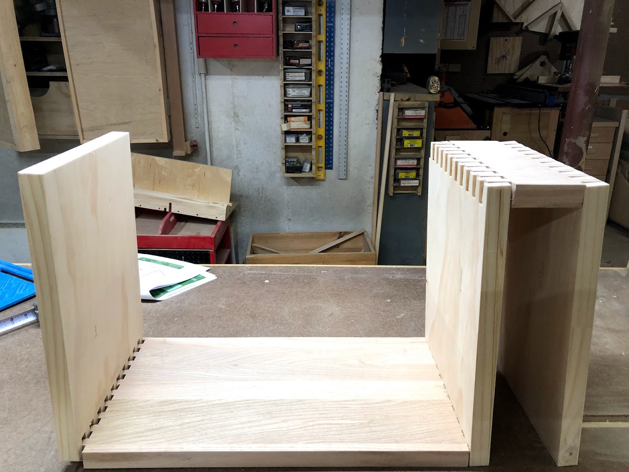
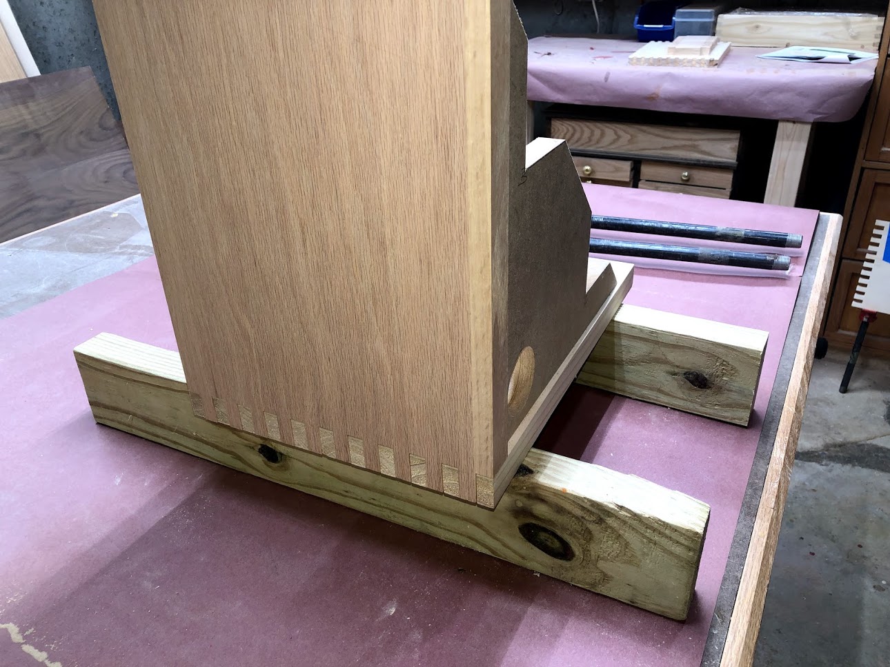
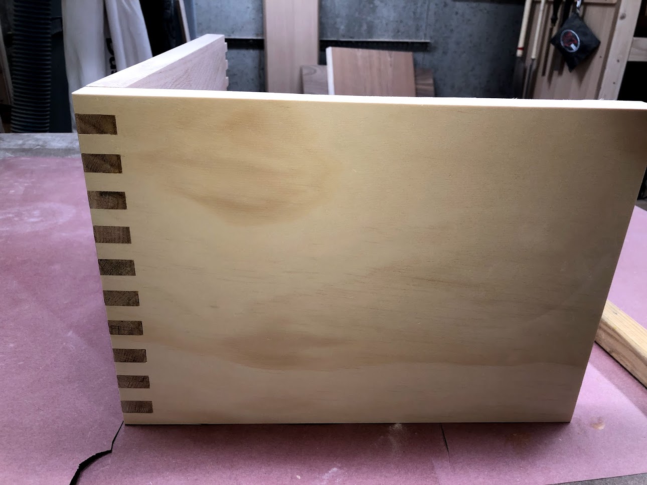
Here are all the parts needed to make the table, 2 oak and 3 pine.. this provided a contrasting color to the box joint when they are cut.
THE BOX JOINT JIG

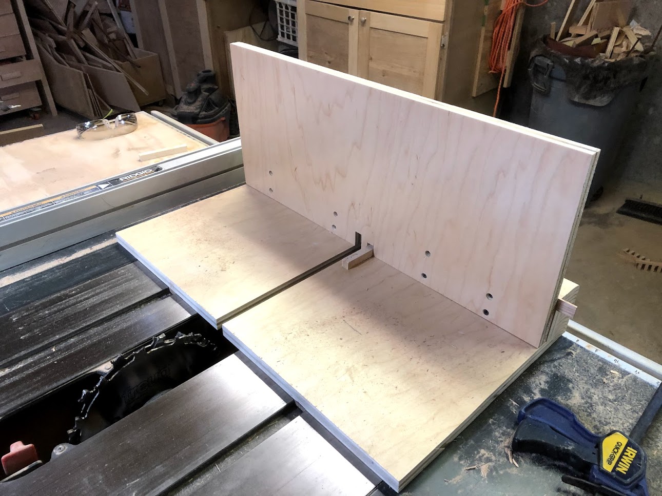
Here is the box joint jig that I made for my table saw

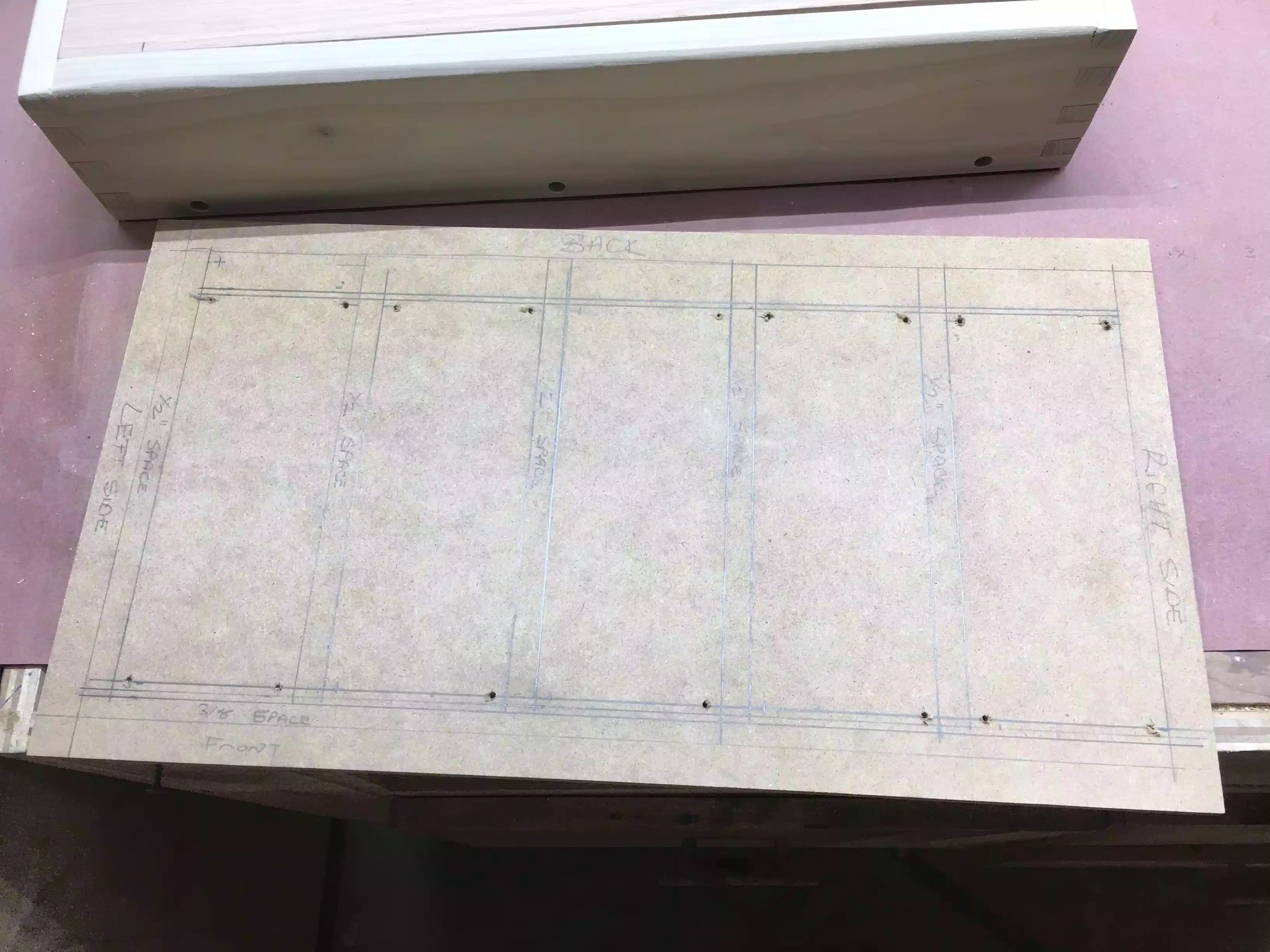
Key spacing and jig dimensions
As far as jigs go this is one of the easiest jigs that you can make, if you decided that you don’t want to make one you can purchase them at Woodworking specialty stores like Rockler or Woodcraft. Some stores only sell them for Router tables and also table saw set-ups but for what they do they are on the procey side ranging anywhere from $70.00 - $180. To make one maybe only cost $25.00.
The jig is basically made up of the following parts:
Table runners (these fit on your miter slots in your table saw top)
A base (usually made with plywood)
A fence that is screwed to the base
A piece of 2x4 that goes behind the primary fence
A wooden key (I used a 1/2” x 1/2” square dowel) you determine the dimension of this key based on what width you want your box joint to be).
If you would like more instructions on how to make your own box joint jig click the below button on step by step instructions, this is not my design but I did make this one.
CUTTING THE BOX JOINT
Cutting the box joints is simple enough but it does require a little methodical thinking to the sequence of doing it. When using the jig and planning on the box joint layout you will need to do the following:
Set-up the table saw by installing a dado stack that matches the width of the finger that you want in your project in my case that is 1/2”, then you will need to raise the dado stack in the table saw to match the thickness of the wood that you are making your project on, in my case that was 1”
Box joints are created by the strategic removal of wood on the end of each board. So if you were to start with a pin on one board, you need start with a space on the mating piece. Below you can see an example Board A has been started of with a finger. To achieve this you will need to register the board edge next to the key on the jig and running the jig through the dado stack in the table saw. You will need to move this board from right to left until you complete cutting out the spaces on the board until you reach the end of the board.
Now that 1 board is done we will need to move onto the mating the board (Board B) so because we started with a finger in board A we need to start by placing a space in board B and so forth all the way until the end of the board. We achieve this by placing a 1/2” next to the 1/2” key that was glued into the jig and run it through the dado stack in the table saw.

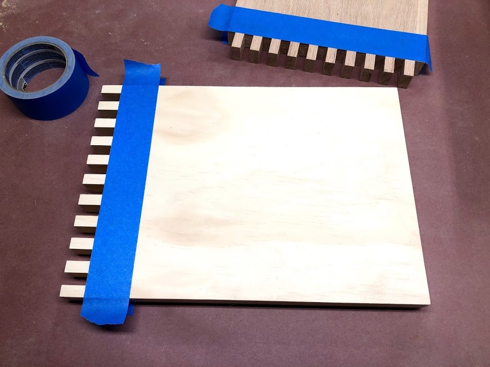
Board A : Shows that I started with a finger and then a space.
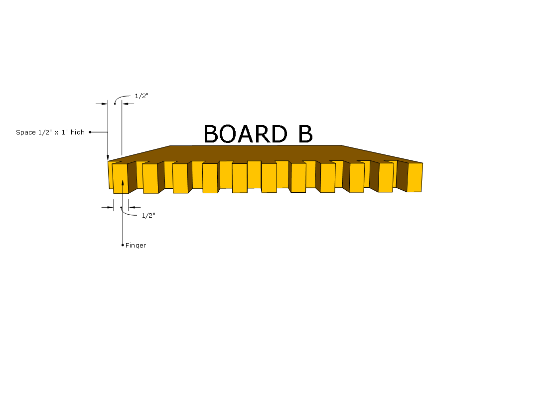
Board B; Shows that I started with a space then a finger, that way both pieces will fit together.

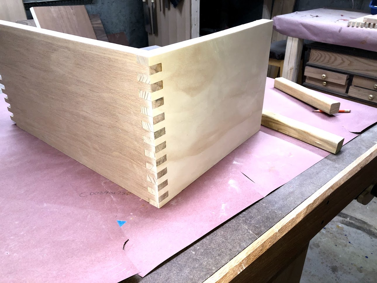
Finally here are you two boards mated together.
I have loaded a video on how to make box joint this is not the jig that I made but I thought the process he used to demonstrate how to cut the actual boards is very useful.
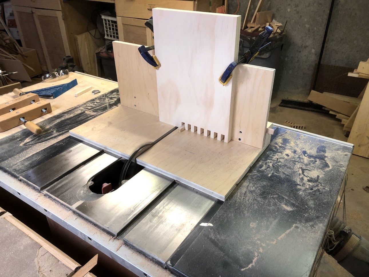
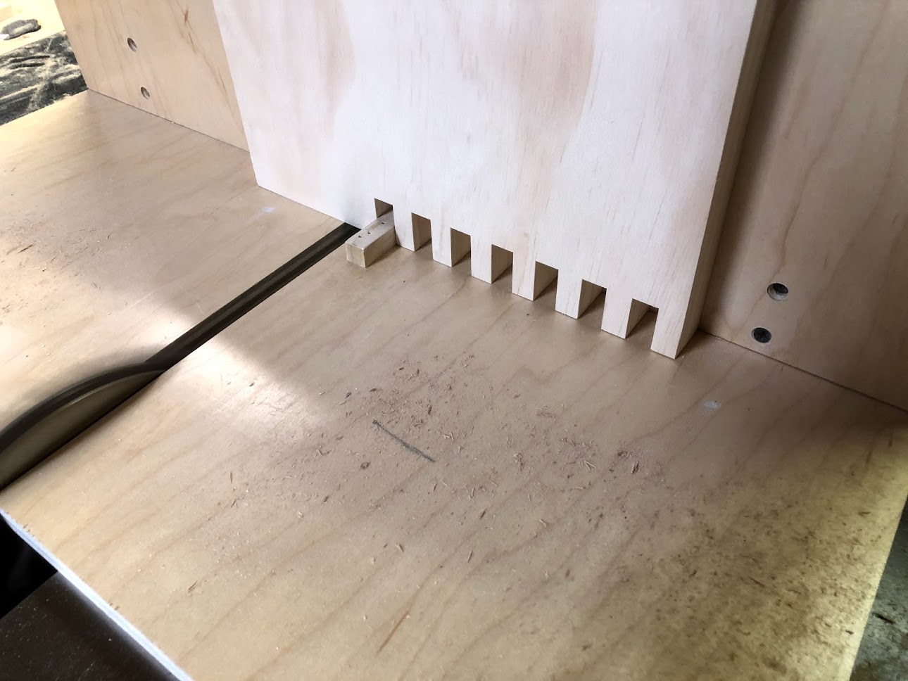
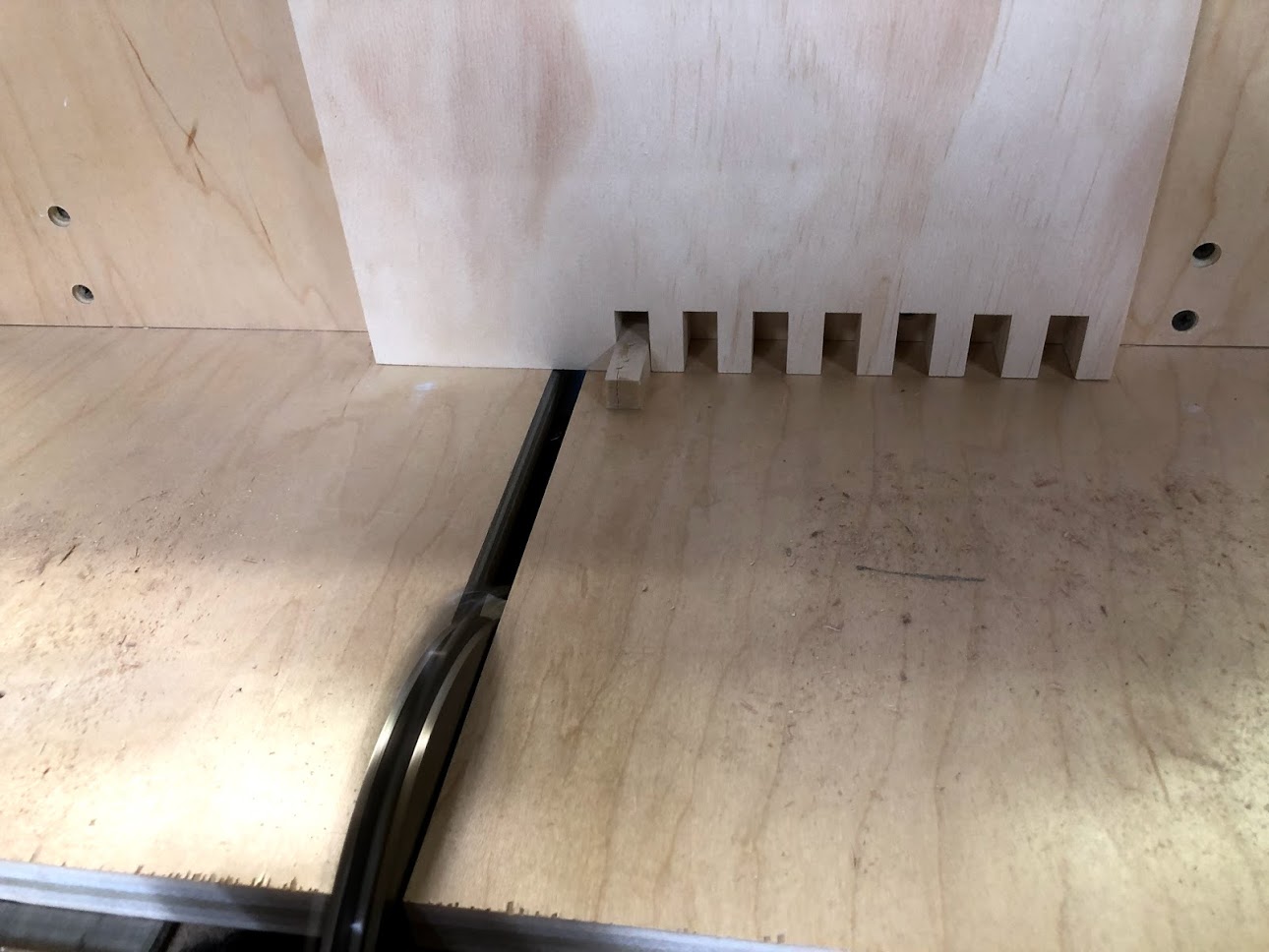
BOX JOINT TIME
So I installed a 1/2” wide dado stack into my table-saw and raised the blade up to approx. 1-1/2” high so as that I can clear the box joint jig and cut a 1” high slot as the wood that I am working on is 1” thick.
Next I placed the box joint jig onto my table-saw and got ready to cut the fingers into my work pieces.
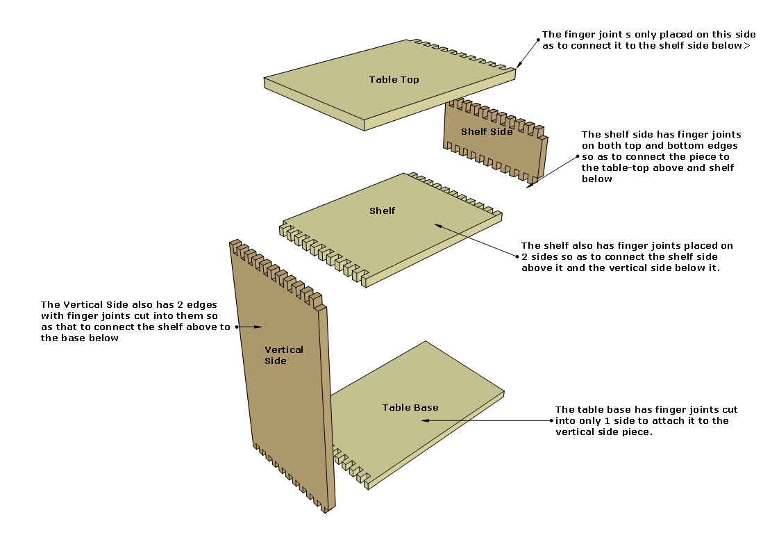
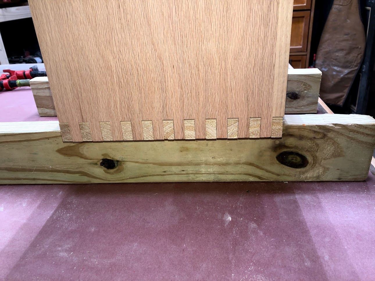
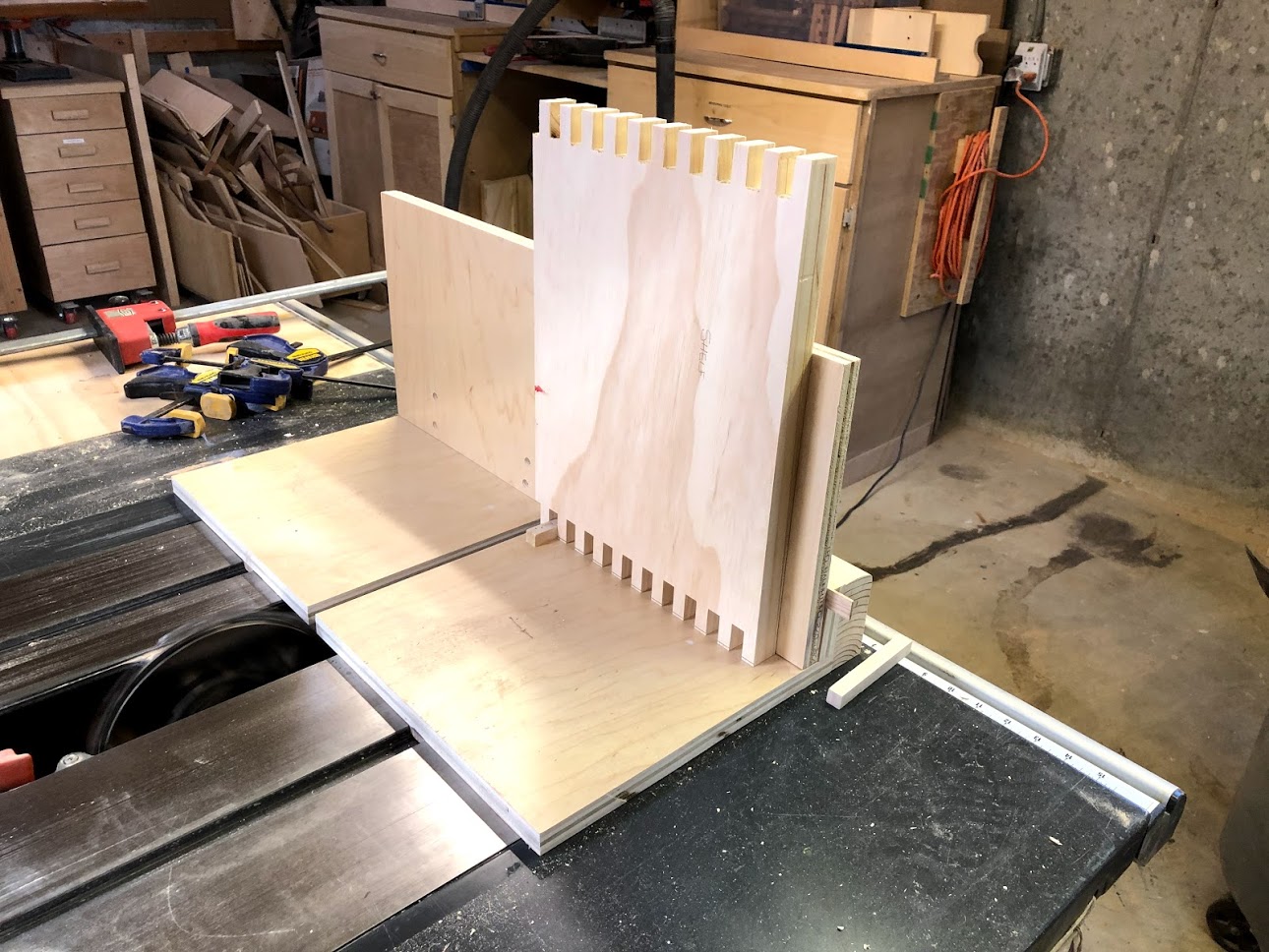
As far as the finger joints were concerned some boards needed fingers cut on both ends and some only needed finger cuts into 1 end, as demonstrated in the image below
DRY ASSEMBLY & CLAMPING AIDS
This project was easy in parts and difficult in others, the difficult part of the project was determining how to clamp it al together. It was difficult mainly because of the joinery method that I choose and that method didn’t not include metal fixings like screws.
The C Table took such a unconventional shape that I needed to do clamping rehearsals to determine where to place clamps and achieve two things which were:
To make sure that I did not put too much strain on the finger joint being worked on to break it before the glue dried and cured completely, to be honest it has taken me 5 days to glue this project together and one day to cut the boards and carve out the box joints in each part of the table.
The second thing that I needed to achieve was that all parts of the table were either plum and/or square to each mating piece. That is why I created clamping jigs to assist while glue each part together.
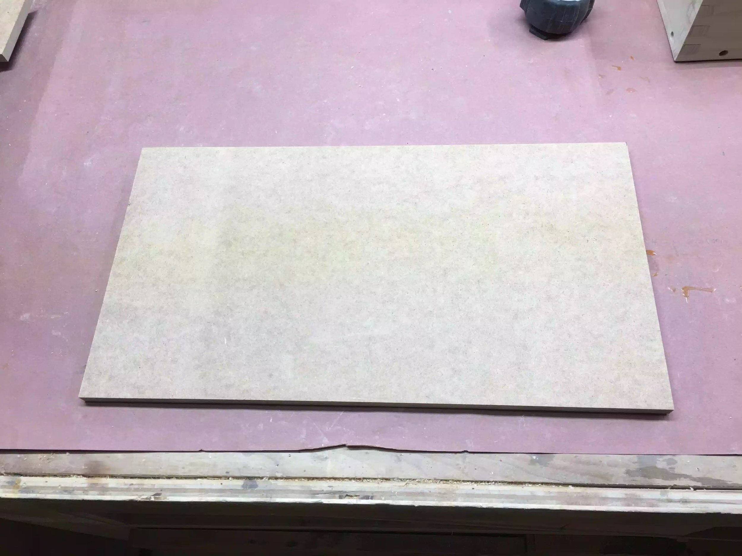
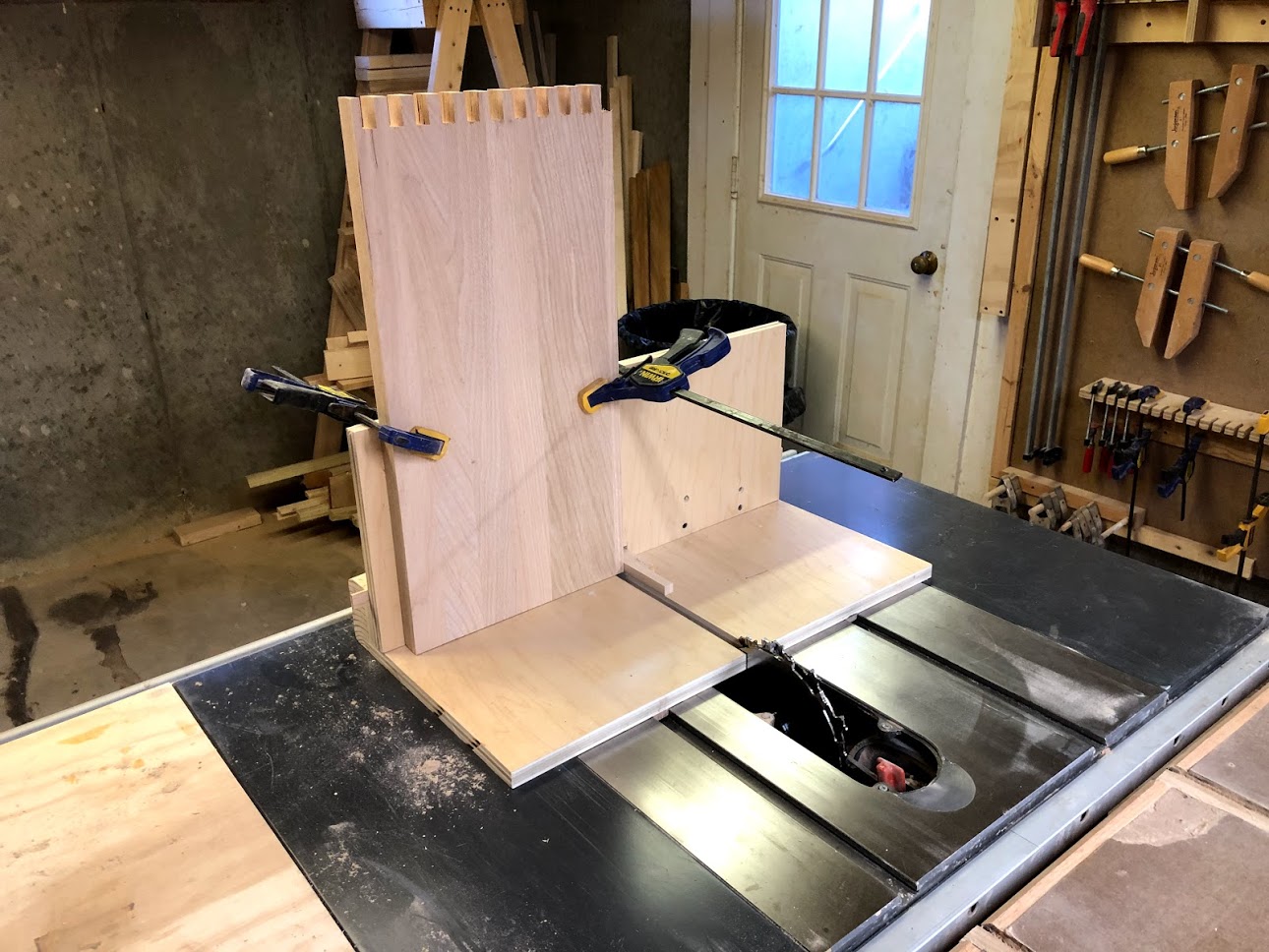
RIGHT ANGLE CLAMPING JIG
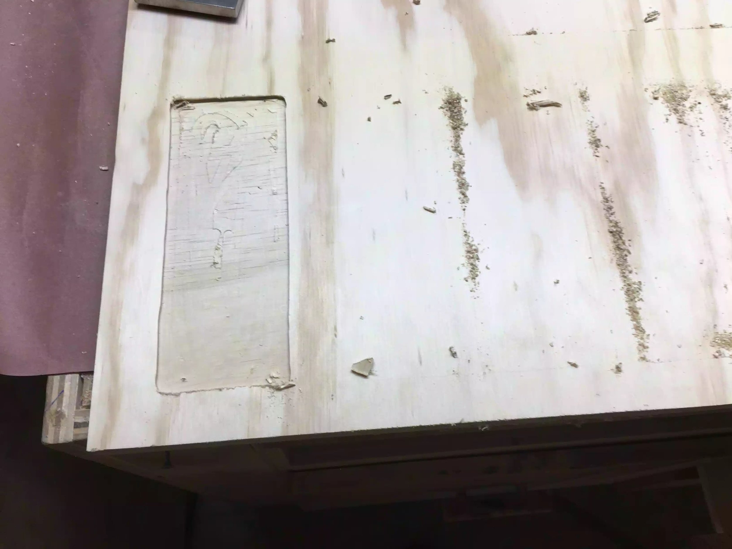
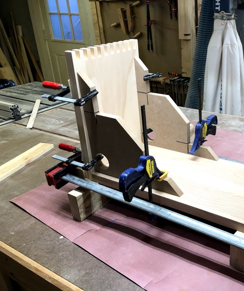
I have made this clamping jig in the past and they are very quick and free to make proving you have some plywood or MDF scraps lying around, I made 6 of these and they were extremely handy when clamping the table pieces together. They basically provide clamping cut outs to attach clamps so as that you can mate 2 pieces together at right angles. Below is a picture of the dimensions needed in making these clamping jigs.


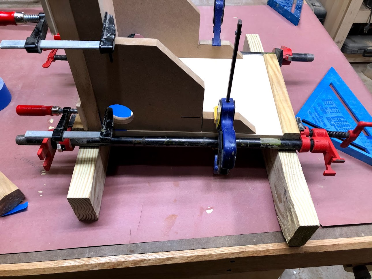
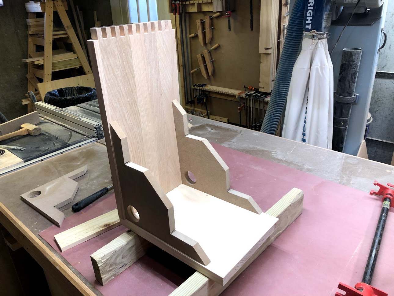
Here is the clamping jig being utilized to clamp the base and vertical side together.

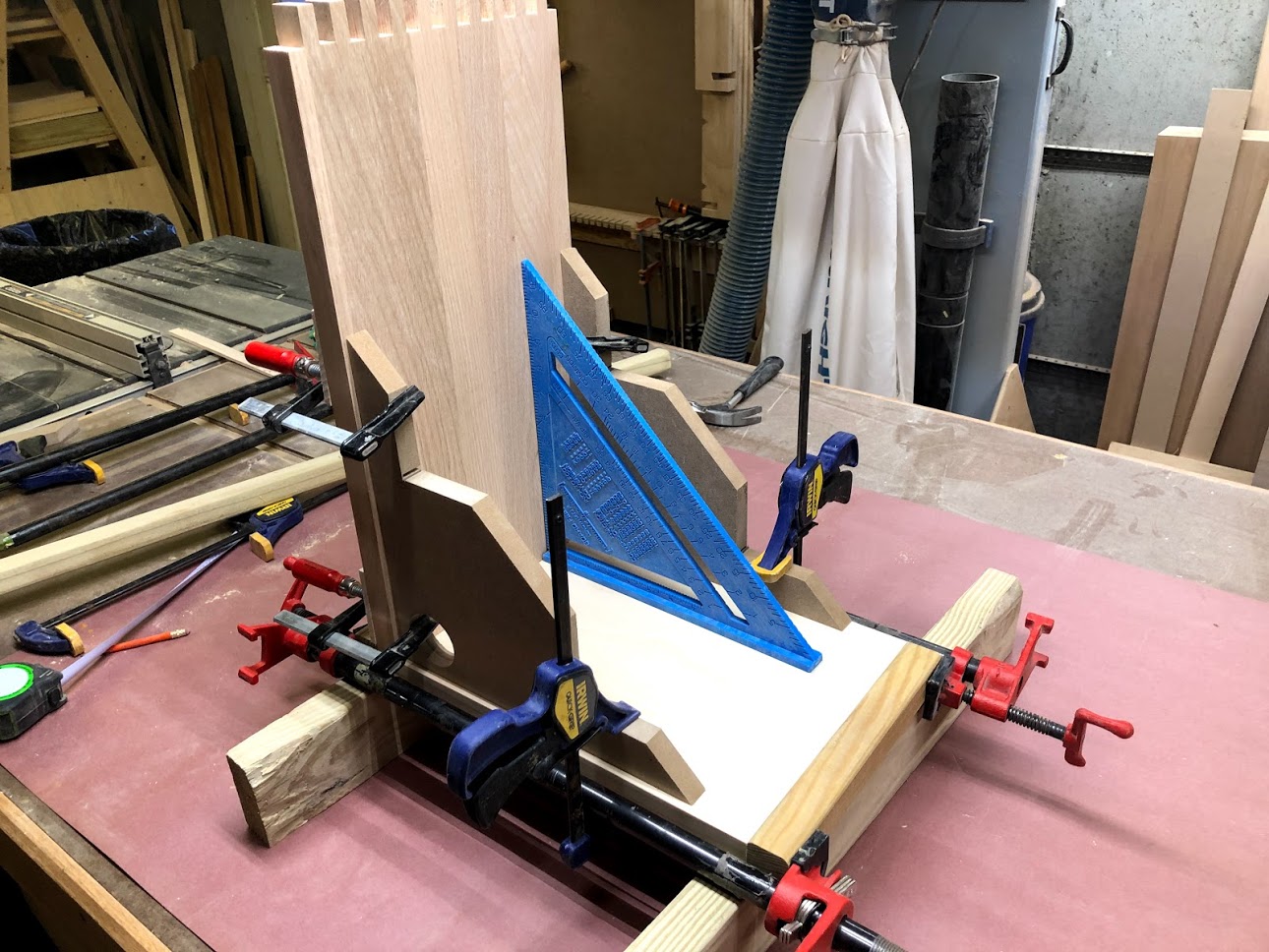
Here is the jigs all clamped up and just to verify that it is indeed 90° using a speed square.
THE GLUE-UP(S)
Like I previously mentioned spent more time gluing the parts of this table together than other section of the project because of having to glue each of he 5 parts of the table separately so as to make sure that I didn’t put to much strain on the glued up joint so as to not break the finger joints that connected the 5 table parts together.
So for the glue up I did the following:
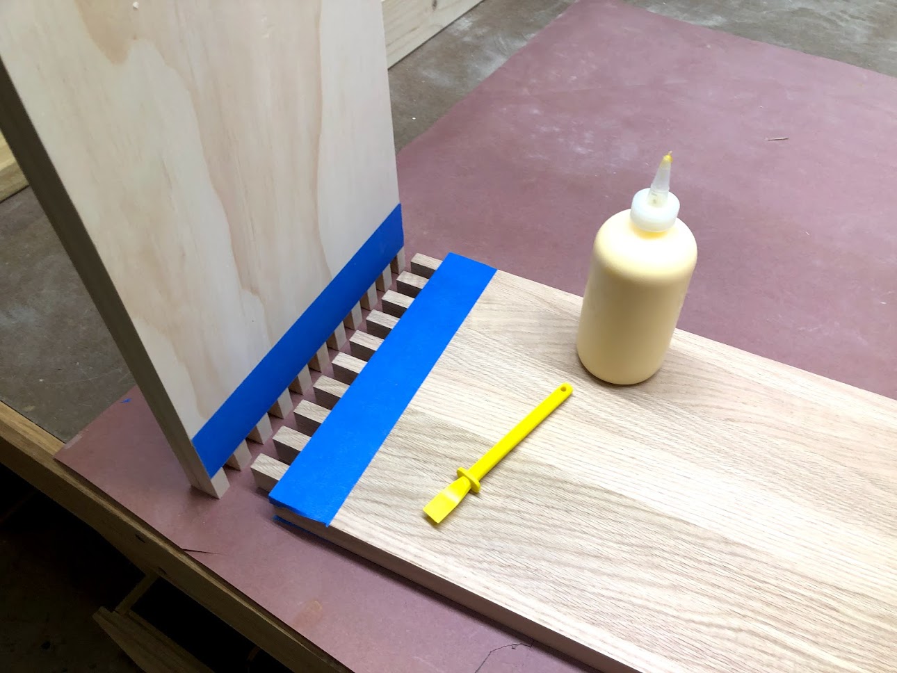
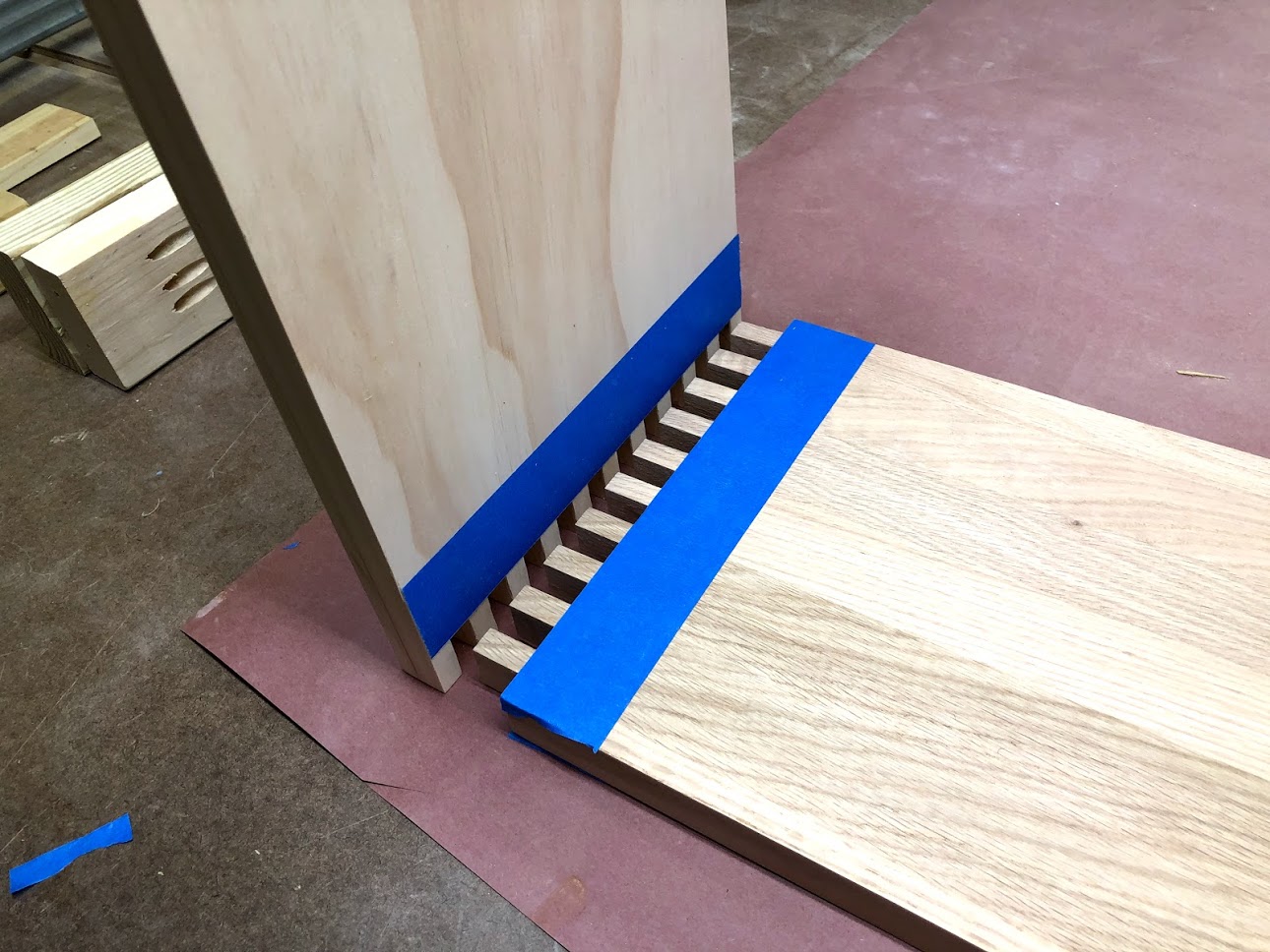
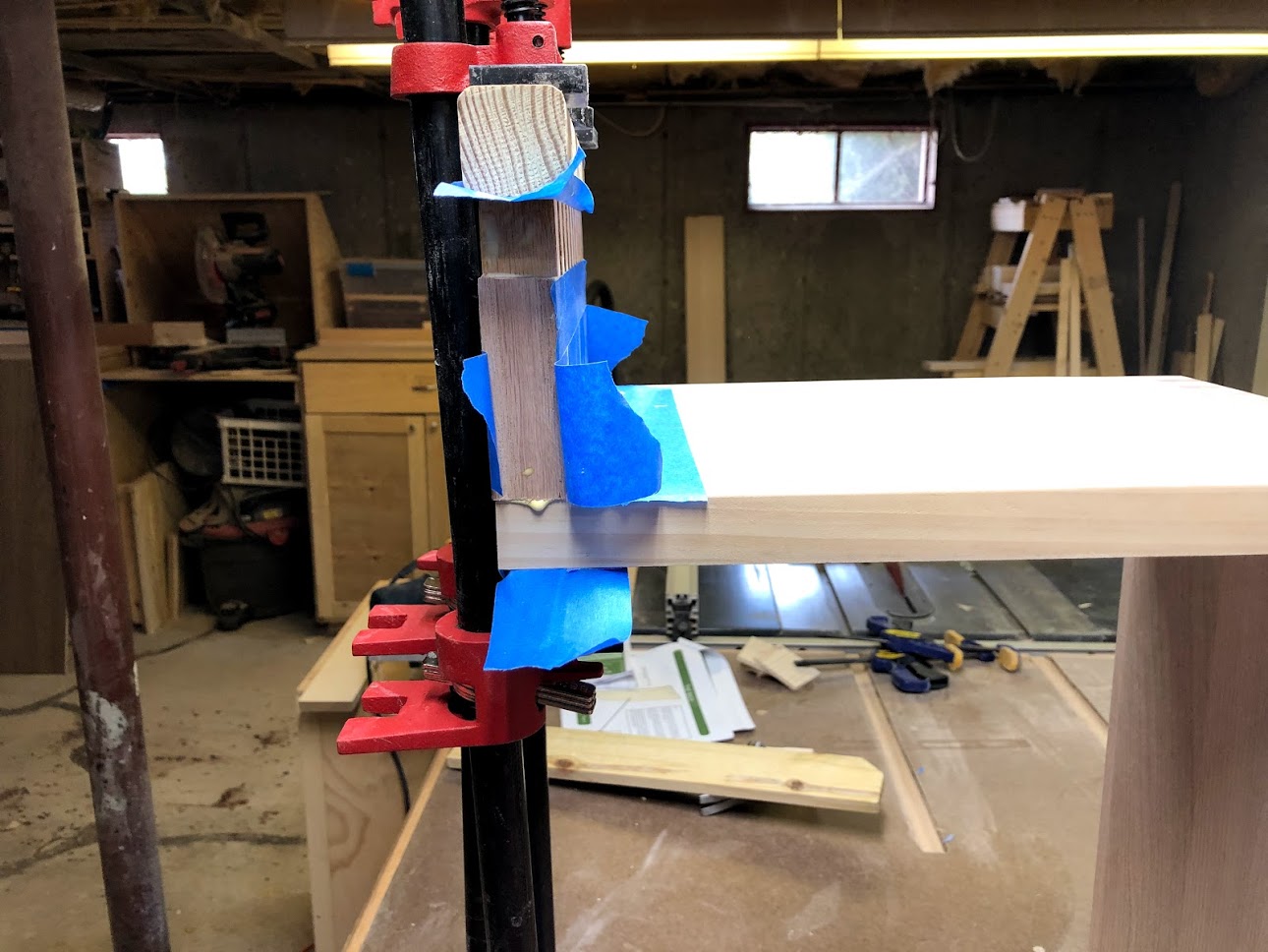
Applied blue painters tape to control the glue squeeze out, I applied the tape to both sides of the mating joints so as that after the glue has dried and cured all I need to do is remove the tape and there is no need to sand and remove dried glue at the corners.
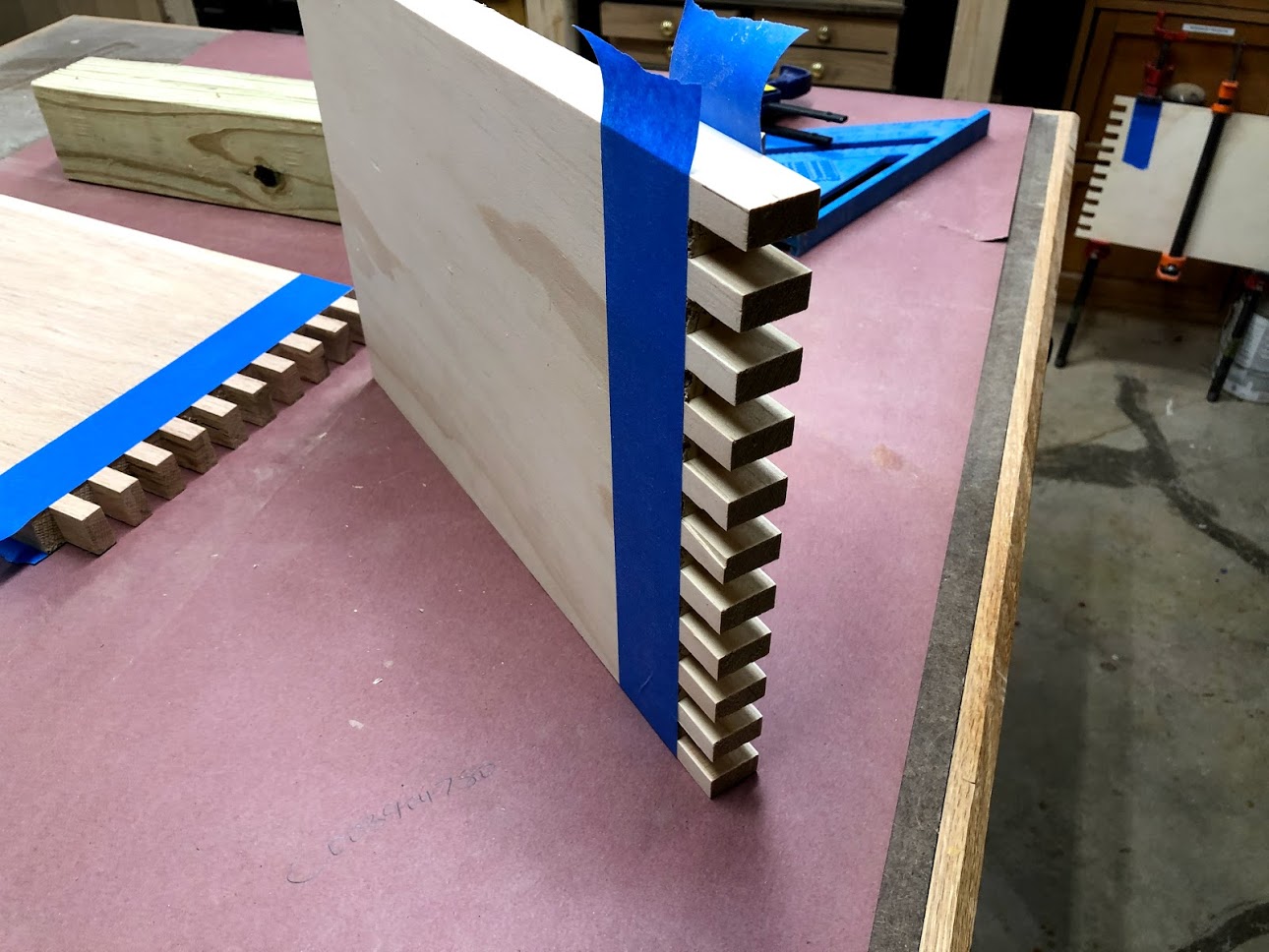
Applied the glue using my little glue bottle and glue stick I applied a little glue to the insides of the fingers making sure not to get glue to any of the visible outside face of the fingers as this is the part of the joint that you will see.
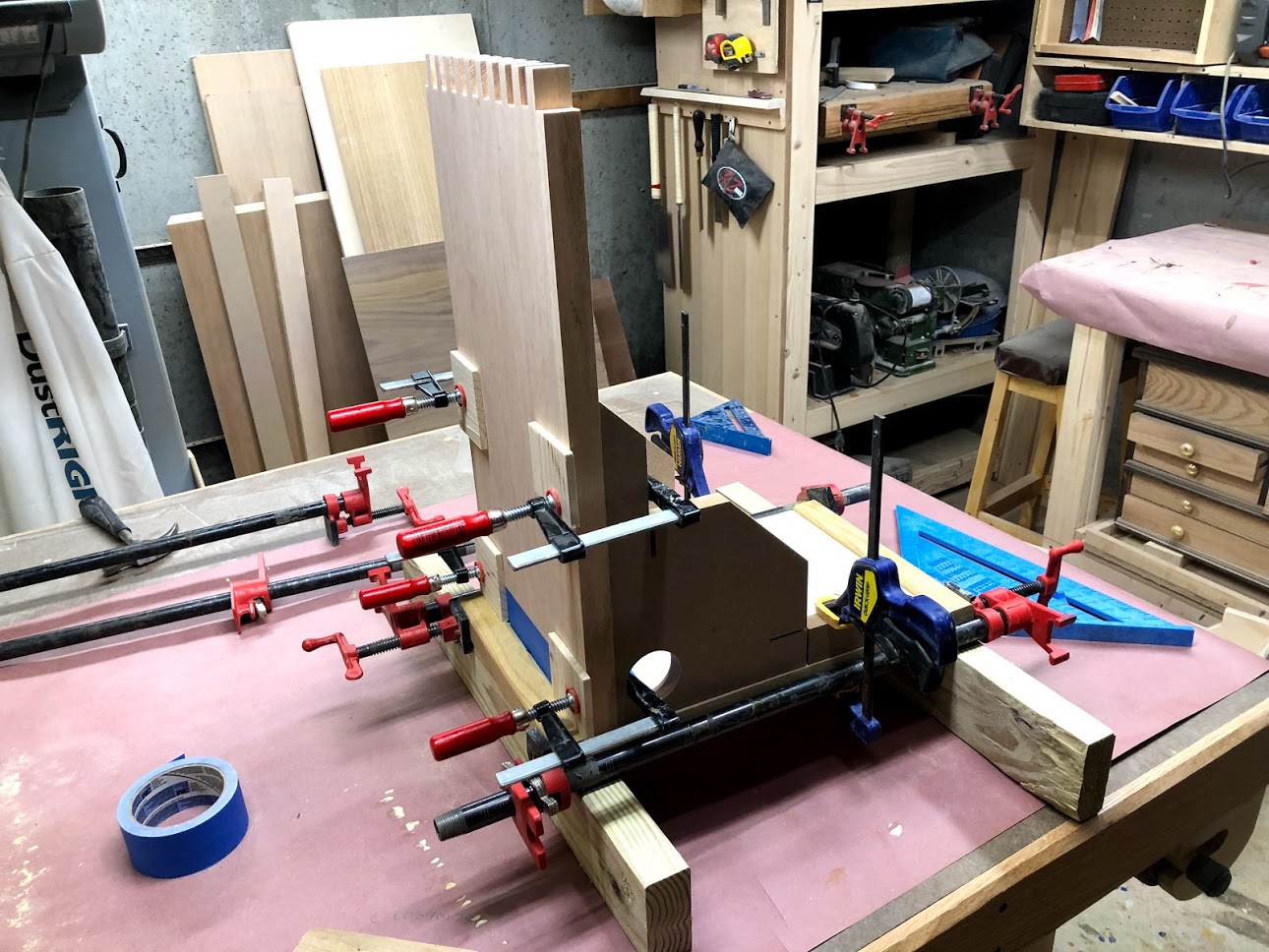
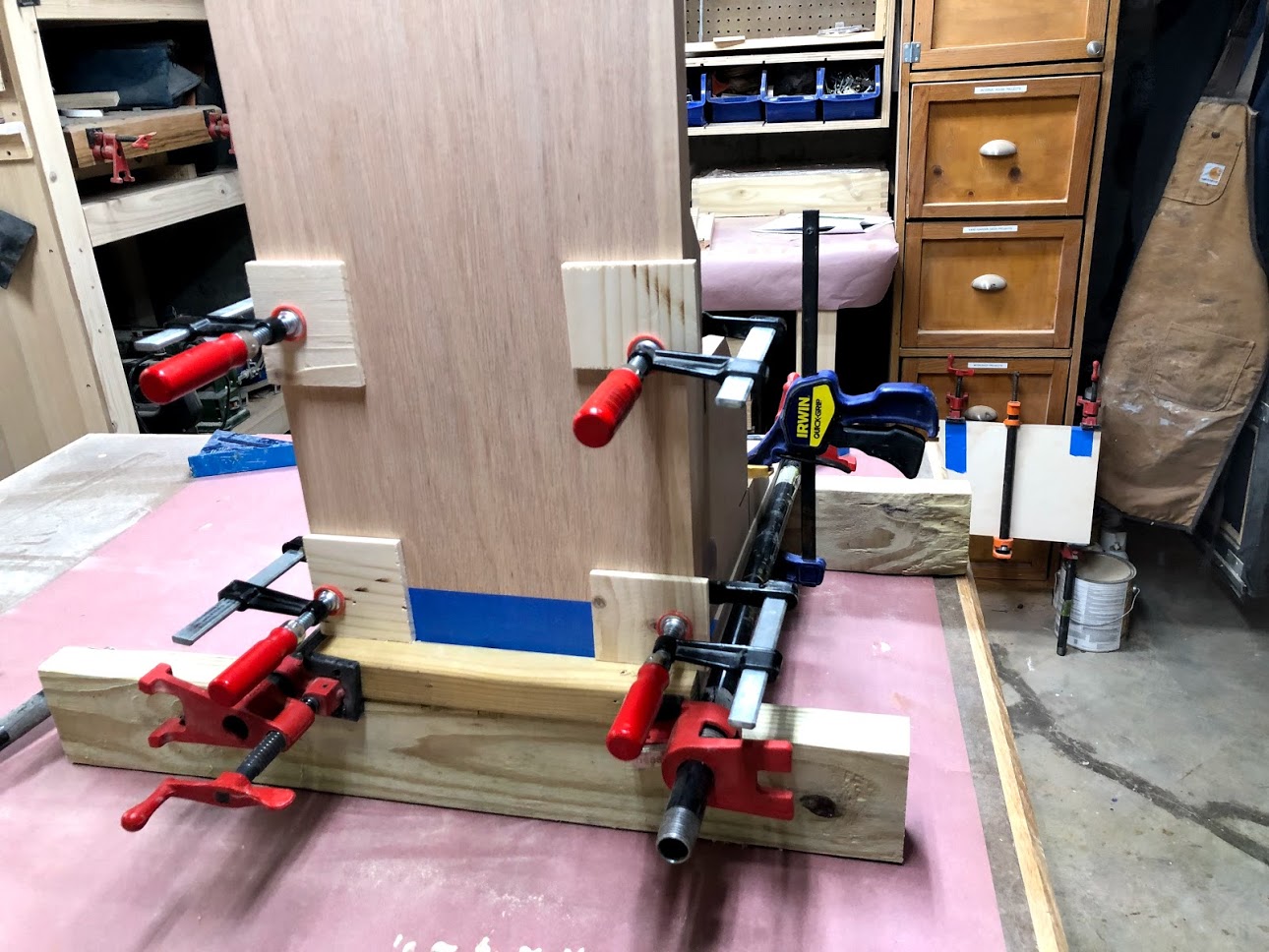
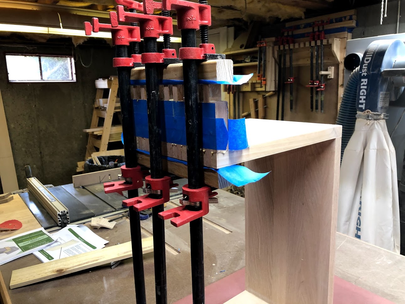
CLAMPING PICTURES
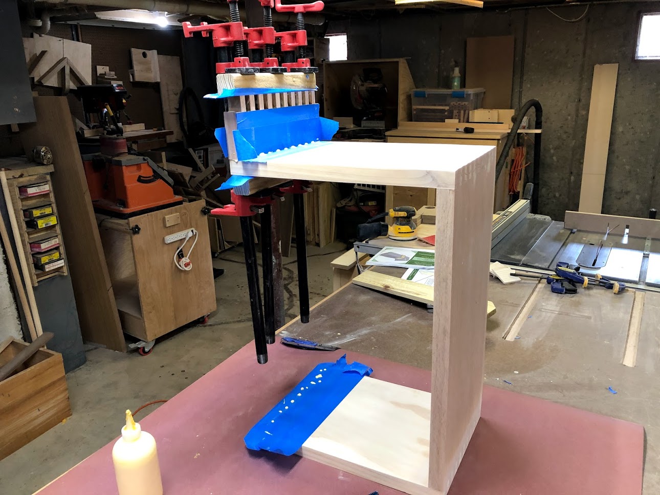
Clamping the Base to the Vertical side
I believe a picture is worth a 1000 words and I think you will get a better idea of how I clamped up this section of the table which the first of many glue-ups coming.

SANDING PHASE
I decided to sand in between each glue up section as it is easier right now to get access to all sections before the table is complete and it will be much harder to sand all surfaces of the table, I started sanding with my random orbital sander equipped with 120 grit paper, then moves onto using a sanding block with 150 grit. After the table is completely assembled I will sand the outside surfaces with 200 grit.
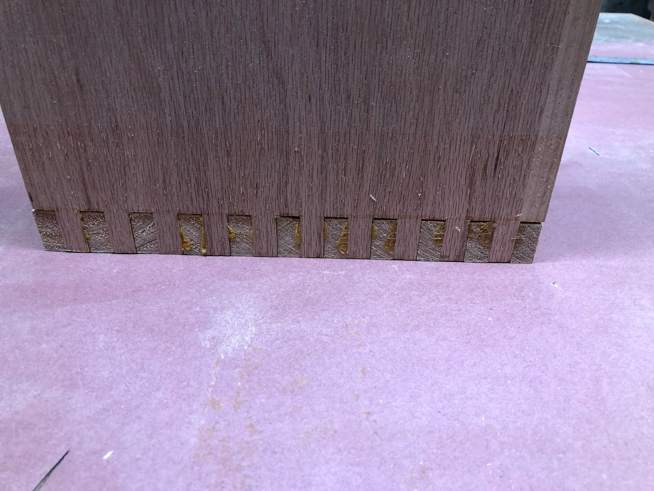
My trick worked with the painters tape quite well but the outside of the joint was ugly and needed some attention.

As you can see I have a somewhat messy finger joint with dried on glue on the fingers, so I will hit this with 120 grit sandpaper and my sander.

After using the 120 grit paper its already looking better. and the finger joint looks nice and tight which is what I was looking for.

Before I started assembly I sanded all parts nut obviously I will need to sand again after the glue up.
To be honest a lot of this project was somewhat rinse and repeat, all parts of the build were some what the same the only difference was what part of the table I was working, the process was as follows:
Apply painter tape to each joint line
Glue up with varying clamping solutions
Remove painters tape after glue
Sand
Below ae a few more pictures of each stage of the build I will not need to explain any further because it was the same as before as listed in the bulleted list above.


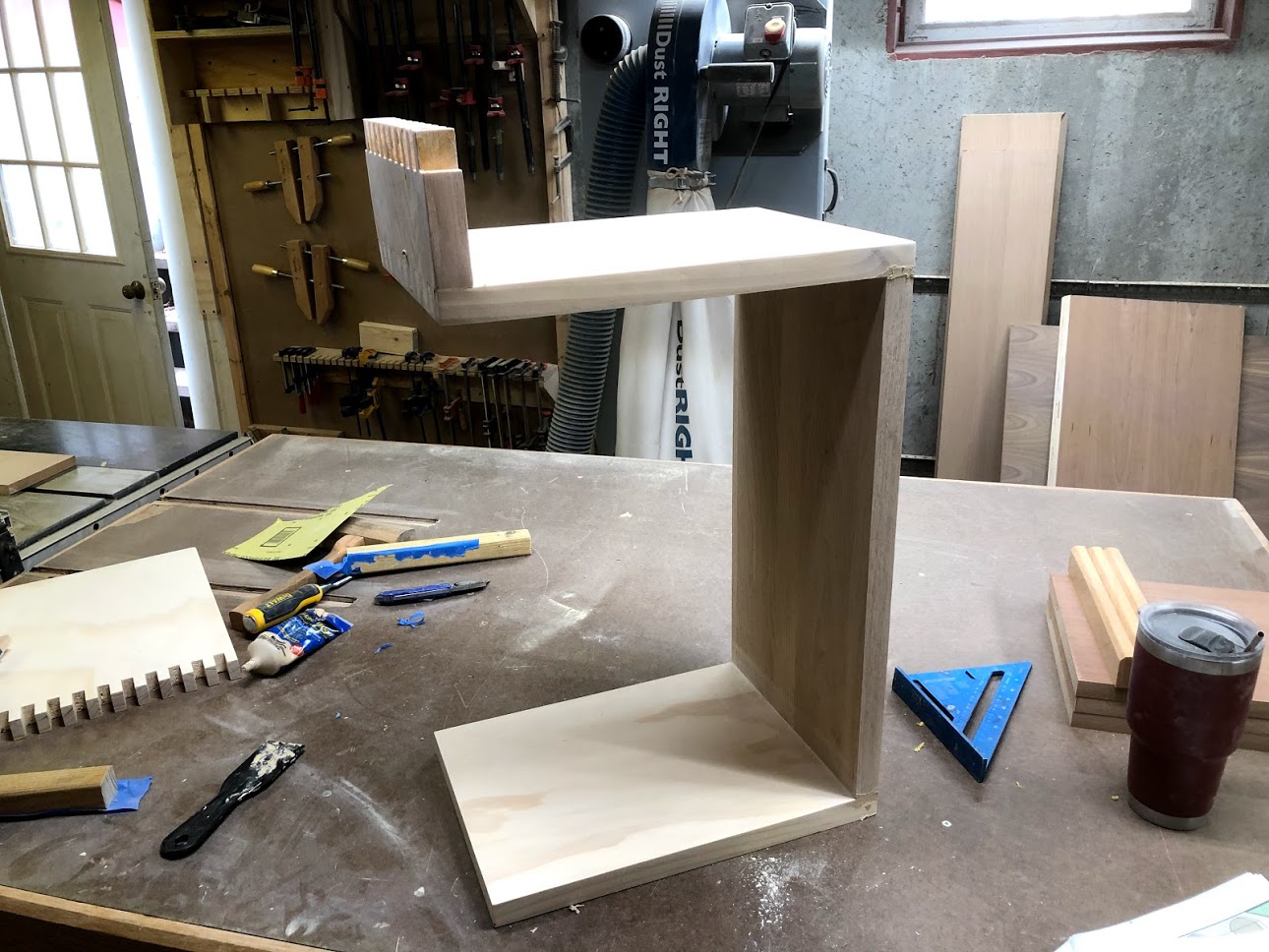
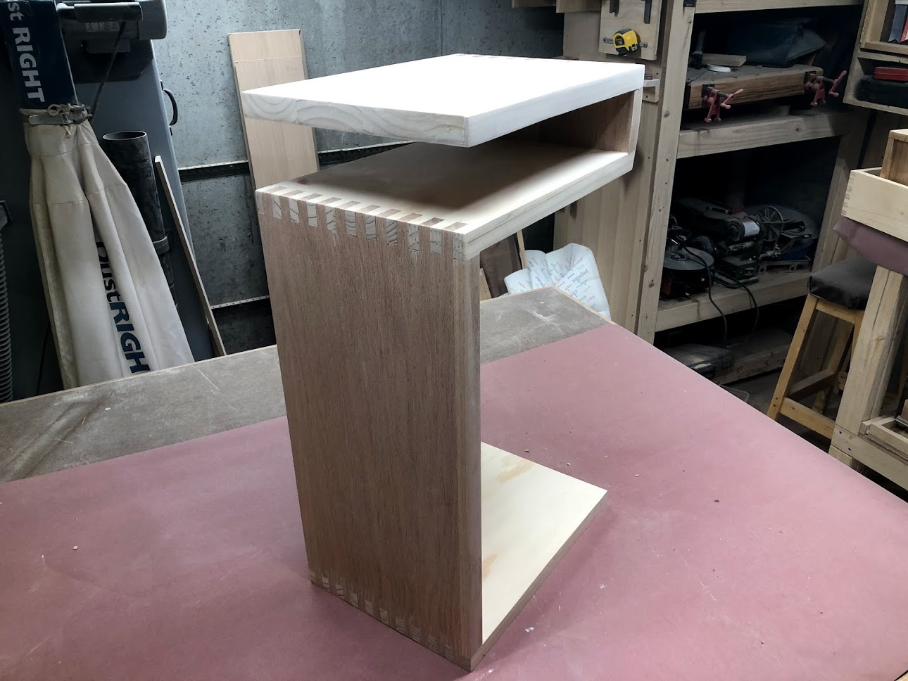
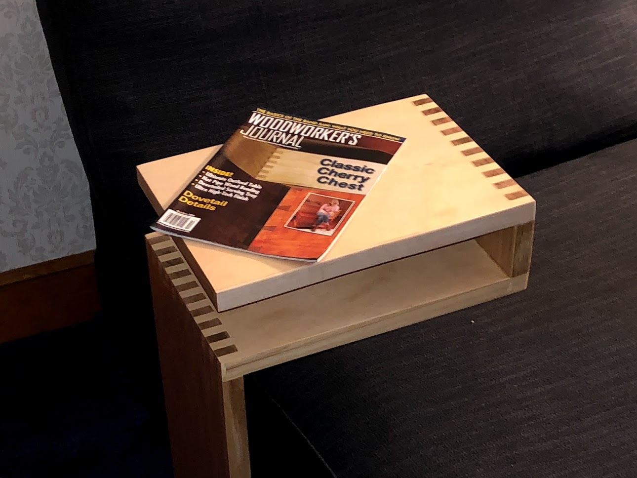
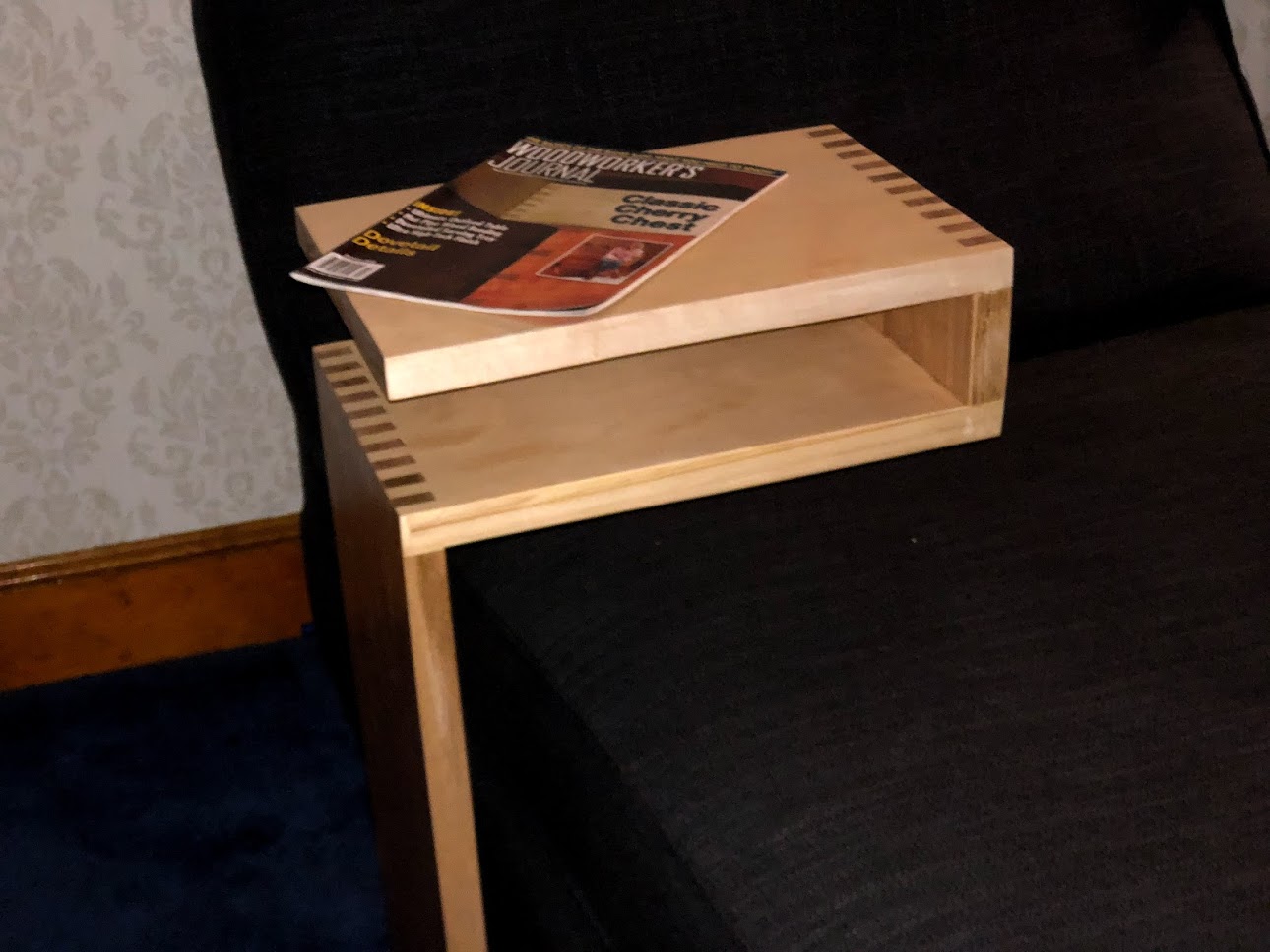
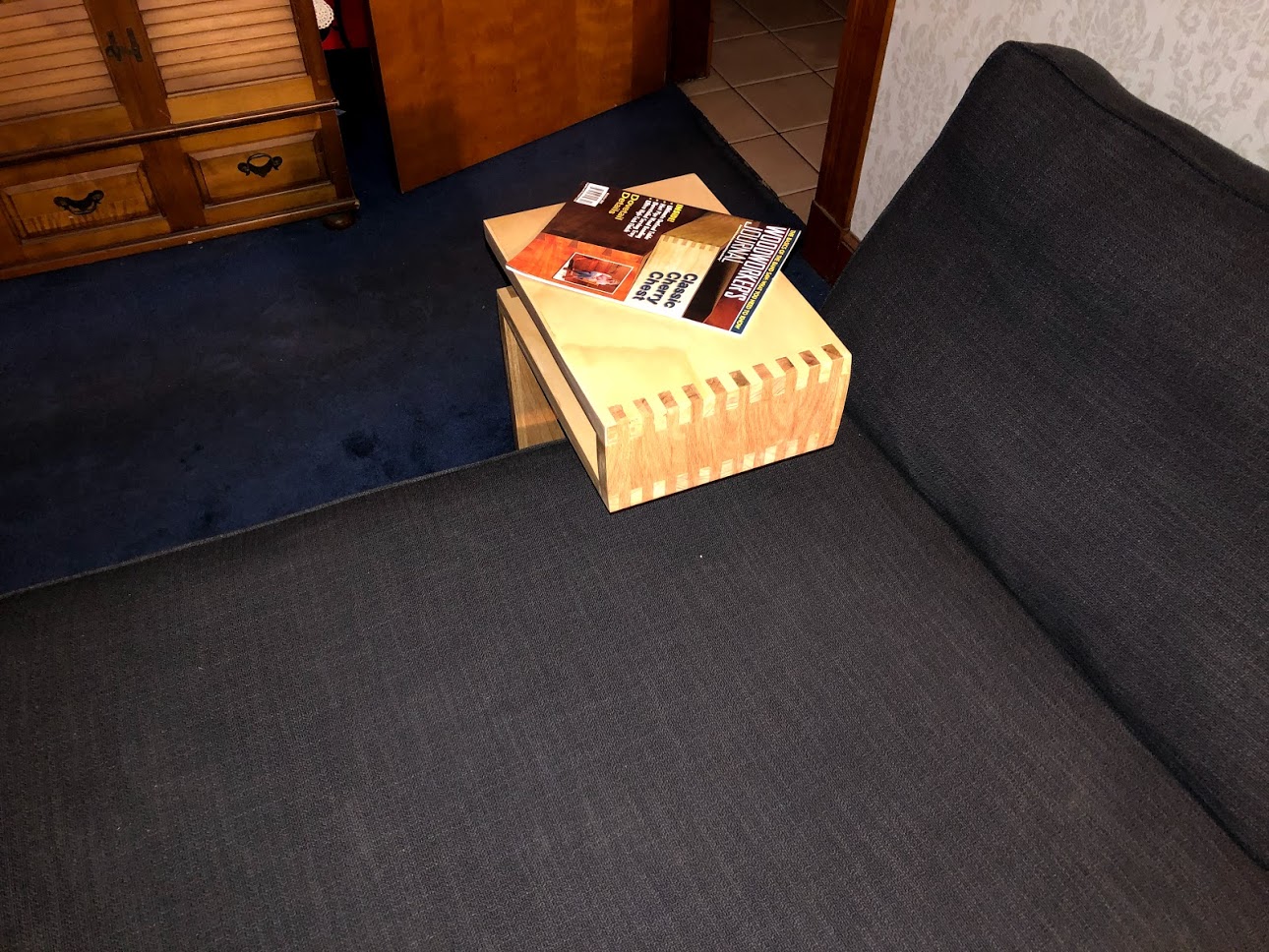
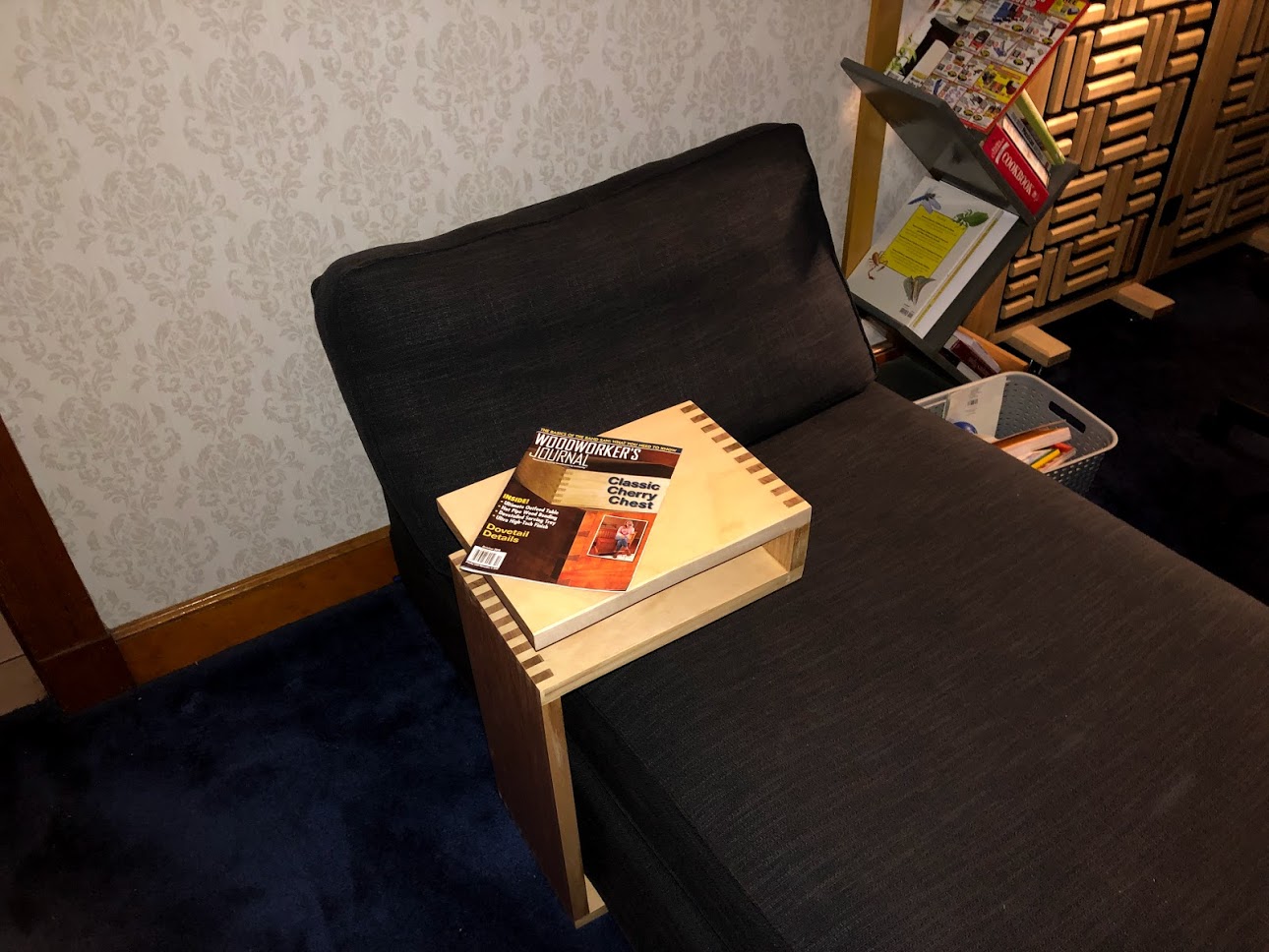
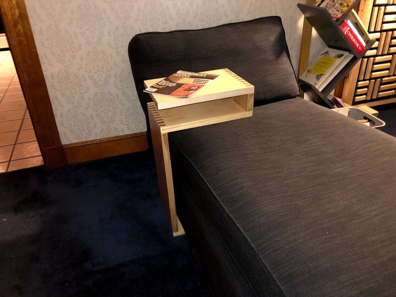
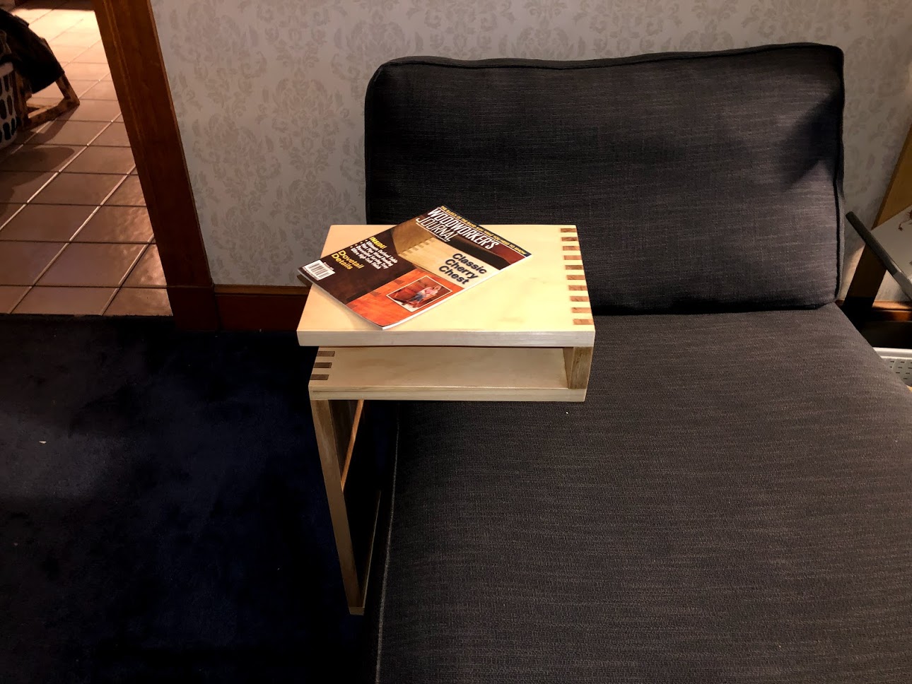
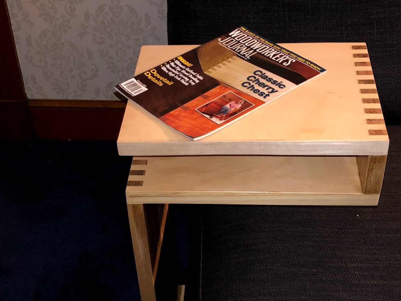
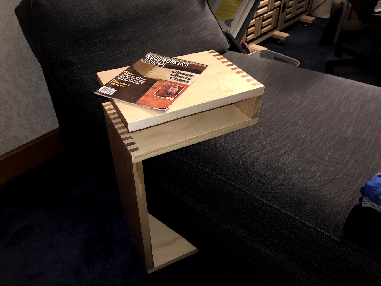
ALL FINISHED
After the assembly was all complete all that was needed was to apply a few coats of finish and in between each coat I sanded with 220 grit paper. I used a total of 3 coats of Minwax Polyacrylic and it came out awesome. My wide loves the new table in here home office and enables here to relax when she can to read or drink a cup of coffee and has somewhere to rest her book or coffe cup.
Below are a few images of the finished table. Thanks so much for reading this project blog and urge you into making one yourself, I had a lot of fun designing and making this piece of furniture and if you want plans to make it I have them available in my shop for download.